Westfield Fasteners Limited Header


Westfield Fasteners Product Specification:

ASME B18.6.3 - UNF Slotted Fillister Head Machine Screws

This product guide contains the specification for UNF thread Slotted Fillister Head Machine Screws, a series of standard parts available from Westfield Fasteners. The basis of this specification is the ASME standard ASME B18.6.3.

Product Description
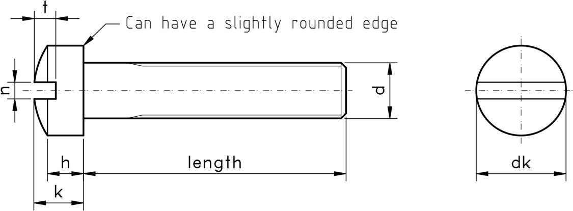
UNF slotted fillister machine screws have a large cylindrical head, with a slightly convex top surface. These Fillister head screws are the preferred head type for counterbored holes and can also be used for protecting a surface by raising the level which the screwdriver is used to tighten the fixing.
A fillister head has similarities to a Pan head machine screw, but the fillister head machine screw has a greater side height, and the height to diameter ratio of the head is larger than a pan head.

Scope of the ASME Standard
Unlike ISO standards, each ASME standard generally covers a range or family of product types. ASME B18.6.3 covers many machine screw types, including these UNF slotted fillister machine screws, and describes the form, dimensions and tolerances, starting from the thread diameter of gauge size 0000, up to and including 3/4 inch.

The slot drive can have parallel or slightly tapered sides.


technical drawing of UNF Slotted Fillister Machine Screw

Figure 1: UNF Slotted Fillister Machine Screw


Table 1: Dimensions & Tolerances for UNF Slotted Fillister Machine Screws according to ASME B18.6.3 (inches)

Nominal DiameterTPIHead Diameter, dkHead Side Height, H Total Head Height, kSlot Width, nSlot Depth, t
maxminmaxminmaxminmaxminmaxmin
0-800.0600800.0960.0830.0430.0380.0550.0470.0230.0160.0250.015
1-720.0730720.1180.1040.0530.0450.0660.0580.0260.0190.0310.020
2-640.0860640.1400.1240.0620.0530.0830.0660.0310.0230.0370.025
3-560.0990560.1610.1450.0700.0610.0950.0770.0350.0270.0430.030
4-480.1120480.1830.1660.0790.0690.1070.0880.0390.0310.0480.035
5-440.1250440.2050.1870.0880.0780.1200.1000.0430.0350.0540.040
6-400.1380400.2260.2080.0960.0860.1320.1110.0480.0390.0600.045
8-360.1640360.2700.2500.1130.1020.1560.1330.0540.0450.0710.054
10-320.1900320.3130.2920.1300.1180.1800.1560.0600.0500.0830.064
12-280.2160280.3570.3340.1480.1340.2050.1780.0670.0560.0940.074
1/40.2500280.4140.3890.1700.1550.2370.2070.0750.0640.1090.087
5/160.3125240.5180.4900.2110.1940.2950.2620.0840.0720.1370.110
3/80.3750240.6220.5900.2530.2330.3550.3150.0940.0810.1640.133
7/160.4375200.6250.5890.2650.2420.3680.3210.0940.0810.1700.135
1/20.5000200.7500.7100.2970.2730.4120.3620.1060.0910.1900.151
9/160.5625180.8120.7680.3360.3080.4660.4100.1180.1020.2140.172
5/80.6250180.8750.8270.3750.3450.5210.4610.1330.1160.2400.193
3/40.7500161.0000.9450.4410.4060.6120.5420.1490.1310.2810.226


For further details, please refer to the ASME standard document for this item.