Blind rivet nut with a flat top, full hexagonal body and open end
This product guide contains the specification for Blind rivet nut with a flat top, full hexagonal body and open end, a stock item available from Westfield Fasteners.
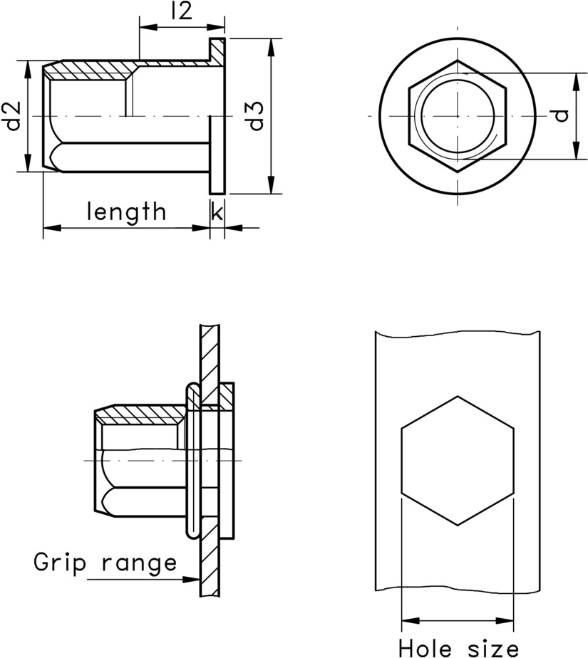
The hexagonal body will need to be installed into a correctly sized hexagonal hole. The open end allows longer length of bolts to be used, which helps combat loosening with vibration.
Used in a multitude of industries such as aerospace, automotive, rail, HVAC, white goods, electronics, as well as the manufacture of heavy goods, bumper systems, seating and vehicle chassis.
Blind rivet nuts are used for attaching a nut onto sheet metals and thin metal gauge parts, such as panels, tubes and castings. The riveted nut will then allow you to attach and detach components easily using the correct sized bolt.
The larger sized rivet nuts can clamp together multiple layers of materials. Blind rivet nuts are also known as riv nuts, blind nuts and nutserts.
Install by inserting the rivet nut into the correctly sized hexagonal hole within the sheet material. Compress the rivet nut using a pneumatic powered or hand rivet nut tool, which grips it firmly to the sheet material.
In the compression process, the thinner walled section without the thread collapses to form a collar on the blind side of the sheet material. This prevents the nut from being pulled back though the hole and fixes it securely to the sheet material.
Like blind rivets, blind rivets don't need access to the back of the material.
The strength of the riveted joint will vary for each application, as factors such as the material strengths, the diameter of the rivet nut, the spacing between the rivet nuts will all effect the final shear and tensile strengths.
The data below supplies typical strength values.
See the table below for the dimensions for sizes from M4 to M12, along with information on grip range, pre-drilled hole sizes, tensile strength and tightening
torque. The tightening torque specifications are guide values depending on the material of the original component and must be checked by testing the component.
The grip range is the total thickness of the materials to be joined.