Westfield Fasteners Limited Header


Westfield Fasteners Product Specification:

ASME B18.2.1 - UNC Hex Head Flange Bolts

This product guide contains the specification for UNC (Unified Coarse)threaded hex head flange bolts or screws, a series of standard parts available from Westfield Fasteners. The ASME standard ASME B18.2.1 covers several fastener types including hexagon flange bolts, and the relevant information for these parts form the basis of this specification.

Product Description
Hexagon headed bolt with a flange. Also known as a washer bolt. The wider surface area beneath the head spreads the clamping pressure and negates the need for a washer.

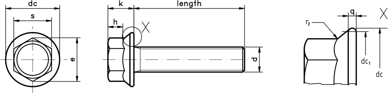
These UNC hex head flange bolts are serrated. The serrations are anti-rotational and bite into the material which they are connecting to secure the fixing.


Scope of the ASME standard.
ASME B18.2.1 specifies the dimensions, tolerances and variation in form for these hex head flange bolts, from thread diameters of 1/4 inch up to and including 3/4 inches. Tables 1 & 2 below define these dimensions and tolerances. Table 3 illustrates the standard thread pitches of each thread diameter for both UNC and UNF threads. Please note that this ASME standard specifies a fully threaded shank for these items.

Material specifications for steel hex flange screws conform with one of ASTM A449, ASTM A354 or SAE J429. Stainless steel variants conform with ASTM F593.


technical drawing of UNC Hex Head Flange Bolts - ASME B18.2.1

Figure 1: UNC Hex Head Flange Bolt


Table 1: Dimensional Tolerances according to ASME B18.2.1 (dimensions in inches & decimal inches)

Nominal Size or Basic Major Diameter of ThreadBody Diameter, dWidth Across Flats, sWidth Across Corners, eMaximum Flange Diameter, dcMaximum Flange Thickness, qMaximum Head Height, kMaximum Hex Height, hMaximum Flange Top Radius, r2
MaxMinBasicMaxMinMaxMin
1/4 (0.2500)0.25000.24503/80.37500.3670.4330.4090.560.040.280.170.015
5/16 (0.3125)0.31250.30651/20.50000.4890.5770.5480.680.050.320.210.019
3/8 (0.3750)0.37500.36909/160.56250.5510.6500.6180.810.060.390.250.022
7/16 (0.4375)0.43750.43055/80.62500.6120.7220.6850.930.070.460.300.026
1/2 (0.5000)0.50000.49303/40.75000.7360.8660.8251.070.080.510.340.030
9/16 (0.5625)0.56250.554513/160.81250.7980.9380.8951.190.090.570.380.034
5/8 (0.6250)0.62500.617015/160.93750.9221.0831.0341.330.100.620.420.038
3/4 (0.7500)0.75000.741011/81.12501.1001.2991.2341.590.110.730.510.045


Table 2: Dimensional Tolerances according to ASME B18.2.1 Continued

Nominal Size or Basic Major Diameter of ThreadMinimum Bearing Diameter, dc1Maximum Runout of Bearing Surface FIM
1/4 (0.2500)0.4800.010
5/16 (0.3125)0.6000.011
3/8 (0.3750)0.7300.012
7/16 (0.4375)0.8500.013
1/2 (0.5000)0.9800.014
9/16 (0.5625)1.1000.015
5/8 (0.6250)1.2300.017
3/4 (0.7500)1.4700.020


Table 3: UNC and UNF Thread Pitch (Threads Per Inch) by Nominal Thread Diameter

SizeThreads per inch (TPI)SizeThreads per inch (TPI)
UNCUNFUNCUNF
#0-803/4"1016
#164727/8"914
#256641"814
#348561 1/8"712
#440481 1/4"712
#540441 3/8"612
#632401 1/2"612
#832361 3/4"5-
#1024322"4 1/2-
#1224282 1/4"4 1/2-
1/4"20282 1/2"4-
5/16"18242 3/4"4-
3/8"16243"4-
7/16"14203 1/4"4-
1/2"13203 1/2"4-
9/16"12183 3/4"4-
5/8"11184"4-


For further details, please refer to the ASME standard document for this item.